 Bally/Midway/Atari Custom Chip Repair
By: John Havel (Cmndr Brain) © 2014
Custom chips suck!!! That's a matter of fact. Bally/Midway and Atari used custom chips in many of their
video games during the 1980's. These chips had a high content of silver in the pins. Now, 30+ years later, many
of these chips are falling apart due to oxidation. The pins are breaking off, many times by just pulling the chip out of the socket. Some cases are worse than others. This procedure is one way to "fix" an extreme case of pin rot on these chips.
WARNING: Use this method with extreme caution. If you are the type that doesn't have any patience, in other words
"can't wait for the paint to dry," do not try this. If you ruin the chip, it's lost. But, for those who have
patience and a some skill at soldering then this should not only fix the chip, but also prevent future problems.
Materials:
Things you will need:
- Safety Glasses
- Dust Mask
- Dremel Tool w/ Re-Enforced Cut Off Wheels
- Small Wire Cutters
- Pliers (preferably about 1/4" wide)
- Pliers - Needle Nose (1/10" wide)
- Rubber Band (about 6" in circumferance)
- Small Vacuum
- Mounted Vise
- Multi-Meter
- Soldering Iron
- Fine Grit Sandpaper (around 600 grit)
- Resistors (sacrificial)
- Pencil
- Ultra-Fine Point Sharpie Marker
- Parchment Paper
- Straight Edge
- Tooth Picks
- Epoxy
- Isopropyl Alcohol
- Tape
- Socket - Machine Pin (same size as chip to be repaired)
- Socket - Standard Dual Wipe (Optional)
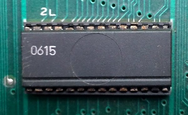
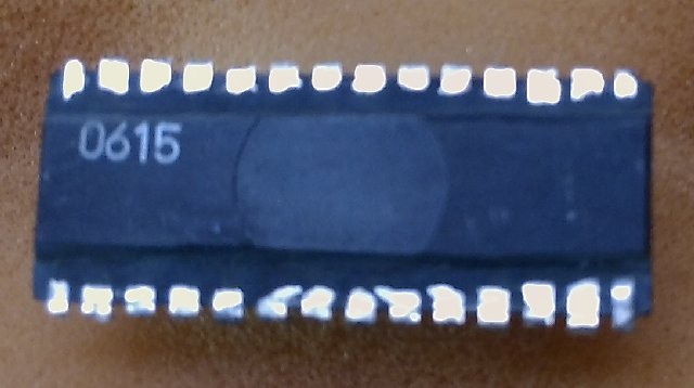
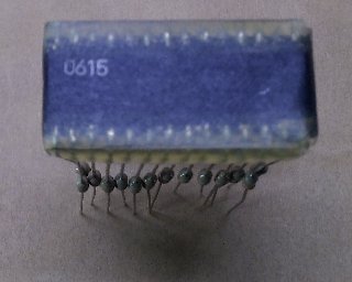
Here we have a custom chip from a Galga board. As you can see, at least 5 of the pins have already rotted off.
Five pins in the top left corner are completely missing.
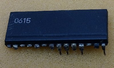
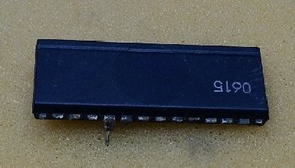
Okay, maybe more than 5 pins. But, here is a good example of what can and will happen to these custom chips.
Getting Started:
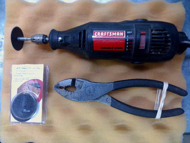
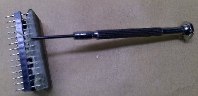
The first tools we need are the dremel with a reinforce cut off wheel, 1/4" wide pliers, rubber band, and a
vice. Wrap the rubber band around the handle of the pliers to hold the jaws shut.
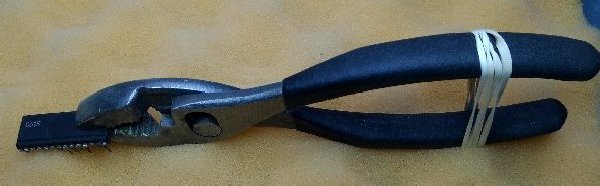
Open the jaws and insert the
custom chip. Try not to place the jaws too close to the center of the chip. If the grip is too loose or too
tight, adjust the number of twists in the rubber band. It should be snug.
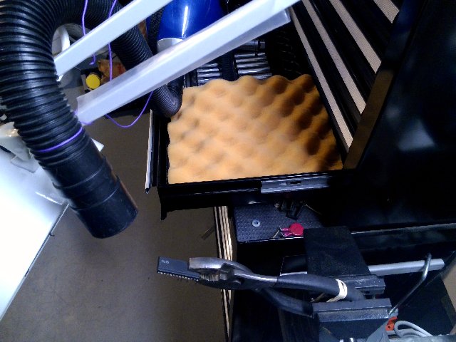
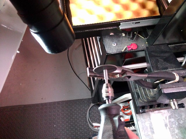
Secure the handle of the pliers into the vise. I rigged up a small vacuum to the work light. This part of the
operation gets very messy. Safety glasses and a dust mask are highly recommended.
Cutting:
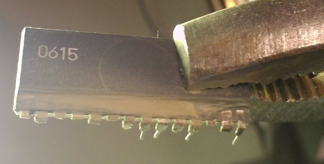
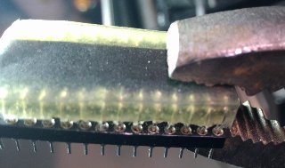
Fortunately this chip has a line already cut into the chip. Using the dremel, cut slightly deeper into the chip along the line. Work slow and careful. Small cuts. Once a small line has been cut into the chip, pull the dremel towards the pins to shave away the plastic package of the chip.
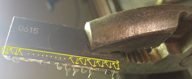
Carefully and slowly continue cutting a line and shaving the plastic until the first of the pin traces are revealed inside the package. The previous picture shows the pattern to cut the chip. This will aid in keeping a slow and steady pace and since my dremel tool rotates the cutoff wheel clockwise, it clears the debris away from the cut area as it passes over.
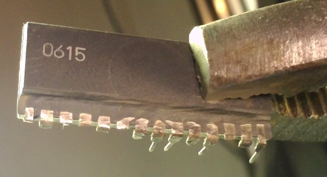
Continue cutting until all of the traces have been reavealed. Be careful to NOT cut too deep.
Doing so will render the chip unrepairable.
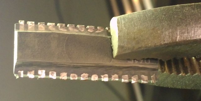
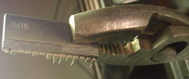
Once all of the traces have been revealed, turn the chip around and expose the other side. The other side will have to be done free hand since there is no guide line. Just cut about the same amount of material as the previous side. This chip has numbers towards the top. Make your first line cut just shy of the numbers. Sometimes, when there are so many pins that have been damaged, weak or broken, it's easier to break off the rest and rebuild the entire chip.
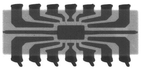
As you can see by this x-ray image of an integrated circuit, there is plenty of trace material before you get to the guts of the chip. But, if you do go too far, damage to the chip may occur. Also, be aware the we are typically working with 24 pin chips. So the traces on the inside are closer still. Also, we're dealing with 24 pin chips and the traces can get a little crowded towards the middle. As long as you don't venture too far to the center of the chip, there shouldn't be any problems.
When the chip traces have been completely revealed, lightly sand, with 600 grit sand paper, any oxidation off the underside of the pins and clean the chip with Isopropyl Alcohol.
Rebuilding the Legs:
We need to prep the exposed pads of the chip in order to rebuild the legs. Using your soldering iron and 60/40 .32mm solder, add a dab of solder to each pad. I've done this with and without putting flux on the pads and see no difference. The solder I use has flux in it.
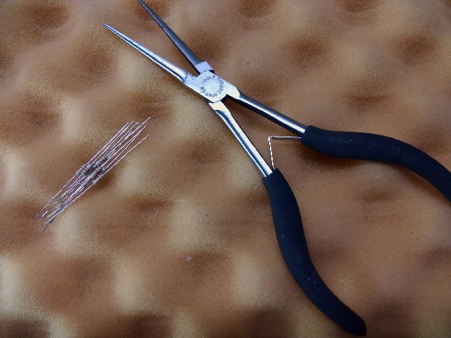
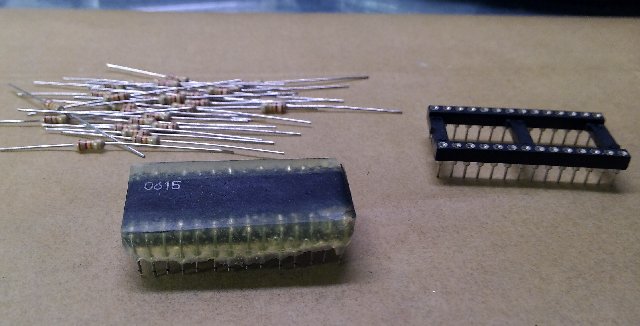
Now for the tools in the next phase. The needle nose pliers I use have a tip that is less than 1/10". This makes it easier not only in this phase of the project, but also later on these pliers can fit in between the pins of the chip after they are rebuilt. You will need 1/4" watt resistors. One resistor for each leg. Since this is a 24 pin chip, 24 resistors are needed. Any value will do because we only need the legs. If done correctly, these resistors will not be useless after.
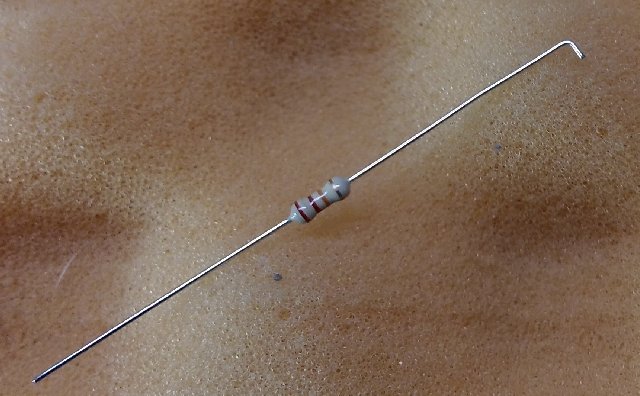
Using the needle nose pliers, bend a very small length of the resistor leg. The bend I use is just the width of the needle nose pliers. So the bend is less than 1/10". After the bending and checking how the first resistor will fit on the chip, bend all the resistors the same way.
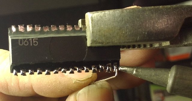
Solder each resistor to the exposed pads of the chip. Make sure that each resistor is perpendicular (90 degree angle for those who don't know) to the chip. Because the pads are so close, be careful not to desolder the previous resistor as you move along. I'm right handed, so I found working from right to left works best.
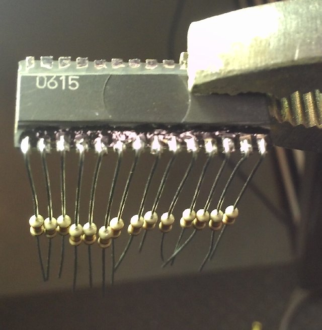
When one side is done, turn the chip around and continue on the other side.
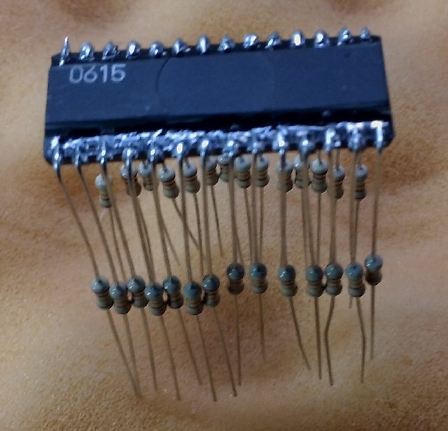
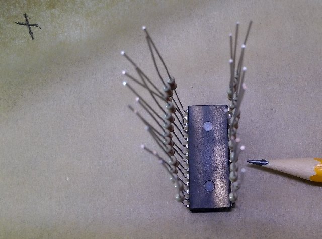
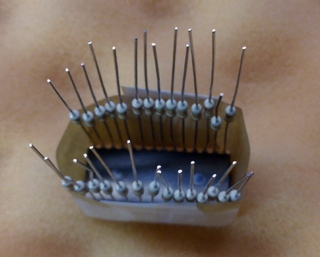
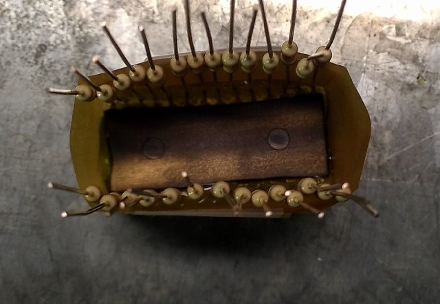
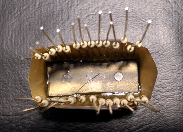
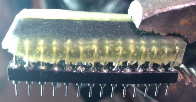
All legs have now been rebuilt.
Now, you could stop there and go straight to the end where you cut the resistor legs
and carefully solder the whole thing to a spare machine pin socket. Or, you could continue
to protect the chip from further oxidation by encasing it in epoxy.
Building the Chip Box:
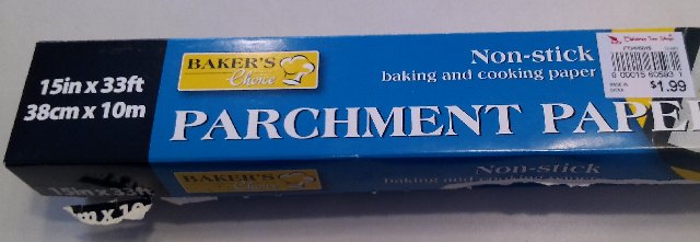
Parchment paper is wonderful stuff. Basically, it's thin paper with a slicon coating. I've found that the stuff at Chrismas Tree shop is the best.
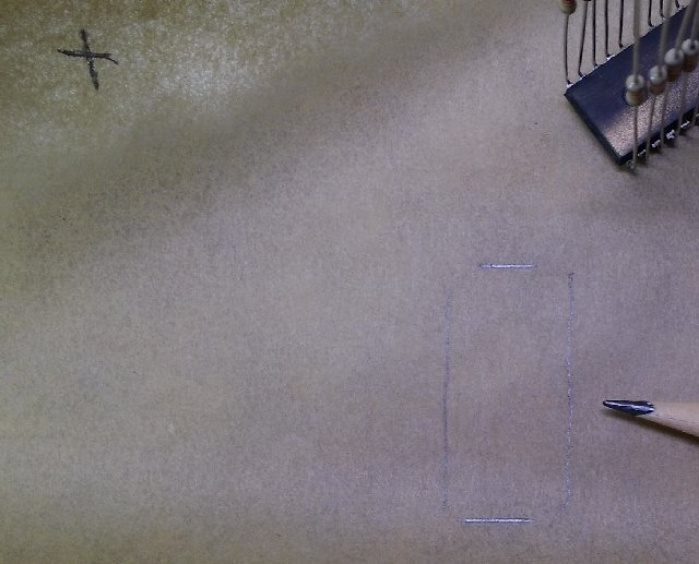
One side of the parchment paper is smoother than the other. On the smooth side place your chip and trace the outline.
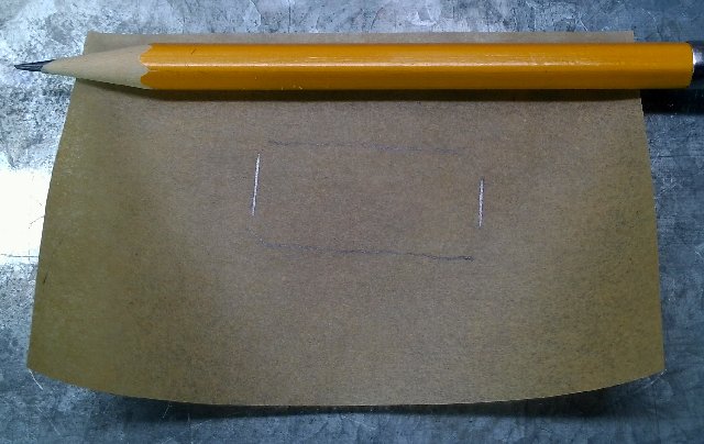

Trim the parchment about 1 inch from each of the traced lines. Crease the paper along the traced lines in both directions.
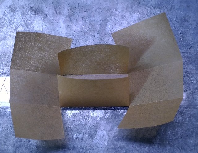
Using scissors, notch the paper along the crease lines on 2 of the opposite sides of the parchment paper. Only cut in to the chip trace/crease lines.
Fold in the newly notched tabs and tape into place. The folded tabs should be on the outside of the box.
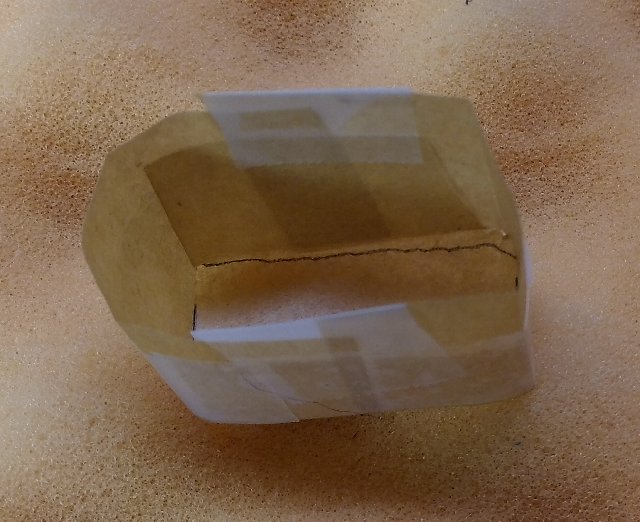
The chip should now fit in the box with very little room to move. Perfect!
Sealing the Chip:
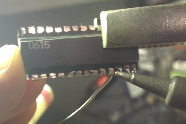
This part of the project will move along quickly. A race against time and the hardening epoxy. Prepare everything before starting this phase of the project. If the epoxy starts to harden, it makes things very difficult. Plan it out and move at a steady pace. Unfortunatly there is no easy way to test your work before you seal the chip, so make sure your connections are good. Use a multi-meter to check for shorts across your soldered pins.
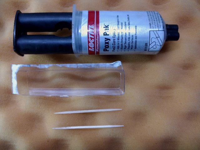
We are going to use a resin epoxy to seal the chip. This procedure will keep the exposed chip pads from oxidizing again and will help support the pads from lifting and the new legs when inserted into a socket. The clear tray is just from a package of a capacitor I bought at a local electronics store. You'll need something disposable to mix the epoxy. The toothpicks are disposable epoxy mixers. The epoxy I chose is by LocTite Fixmaster. It has a high temperature resistance. These chips do get warm, but not very hot. It sets and cures fast. Not necesarily a good thing, but if you prepare everything before hand, it works well. Most importantly, because it's a resin epoxy, it's non conductive. I've tested samples before and after the epoxy is hardened and it does not conduct at all. Don't want to short out the pins. Also, after it hardens, you can still see through thin layers of the epoxy and can still make out the chip numbers.
This part of the project will move along quickly. A race against time and the hardening epoxy. Prepare everything before starting this phase of the project. If the epoxy starts to harden, it makes things very difficult. Read through all the steps before starting. Plan it out and move at a steady pace.
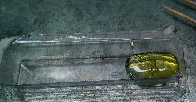
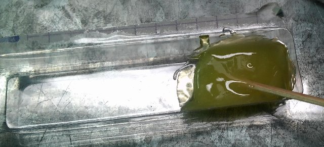
Squeeze out equal amounts of the resin and hardener into the disposable tray and mix thoroughly. You do not need a lot of epoxy. As you do more chips, you'll get a better feel for how much. Although to begin, more is better. You don't have to use it all. I would do this with some scrap parchment paper underneath to prevent any epoxy leaks from ruining your work surface. If you built and taped your box well this shouldn't happen, but mistakes happen.
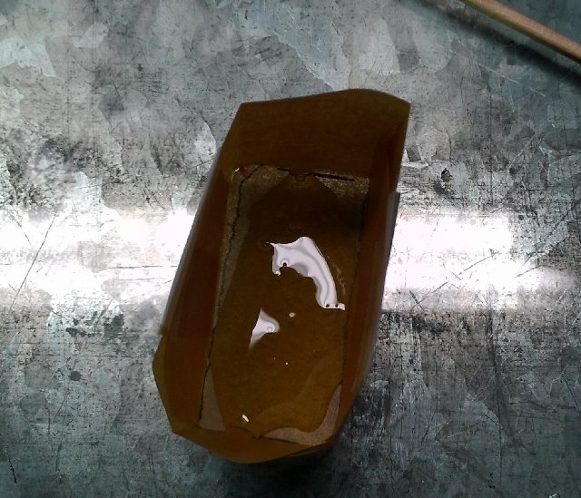
Pour out the epoxy to coat the bottom of the parchment paper box you made. The epoxy on the bottom should only be less than 1/10" deep. Try to evenly coat the whole bottom, but trying to move quickly there is no need to make a masterpiece.
Place the chip, face down in the box and press the chip down into the epoxy with a dry toothpick. Hold the chip down for a couple of minutes. Since the parchment paper is flexible, pinch the sides around the chip and try to get the epoxy evenly distributed around the chip. To make things difficult, try NOT to let the epoxy rise up around the resistor legs too far. Set aside and let harden for about 24 hours. I wouldn't wait any longer. I've noticed that at around 24 hours the epoxy still has a little plyability to it, where as after about 48 hours the epoxy in completly hardened.
Unwrapping Your Present:

After about 24 hours the epoxy should be well set. Carefully unwrap the package to reveal a sealed custom chip.
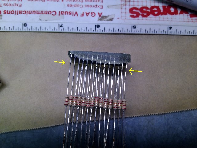
Using a ruler and a ultra fine sharpie marker, draw referance cut lines on the resistor legs. This should be about 1/10" to 2/10" from the bottom of the epoxy overflow. Now you can see why not having a lot of overflow in the prior steps is important.
Using small wire cutters, cut the legs evenly on or just below the referance lines. As you can see in the picture, the resistors still have enough wire on them to be used. You can even use the other, uncut, side to rebuild another chip and still have a usable resistor.
Final Assembly:
Place the chip in a machine socket. Line up the legs and carefully press into the socket. It does not have to be pressed completely to the bottom of the socket. Then use a pick or small screw driver, pick away at the epoxy overflow to clearly expose the leg where it goes into the socket.
Placing the assembled chip back into the pliers and vise, solder the legs of the chip to the socket. Be aware that even though the epoxy is heat resistant, it does get a little rubbery under extreme heat. Go slow and let the epoxy cool down a little between every couple of legs. As you will see in the next picture, I pinched the epoxy with the small pliers and cracked the epoxy.
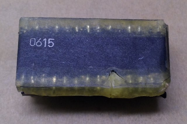
Finished. As you can see, the chip is completely sealed and you can still make out the chip number. You can now insert the chip into the boardset to test it out. I recommend letting the chip set and completely cure for another 24 to 48 hours before extended use.
Final Assembly:


Here is the finalized chip installed and working. It may not look like a masterpiece, but with these chips rotting and getting harder to find, this is a great alternative.
End:
Okay, so this is an extreme case of pin rot. This procedure can be done to fix only 1 pin or just a couple. Instead of cutting and exposing all the pins, you could carefully just expose the pad of the pin that is broken. For that you might want to use smaller cutoff bits. Solder a new leg on and use just a tiny amount of epoxy to cover the exposed pad.